|
Recommendations for the design of hybrids
(from the bonder's perspective)
: - Design and layout considerations -
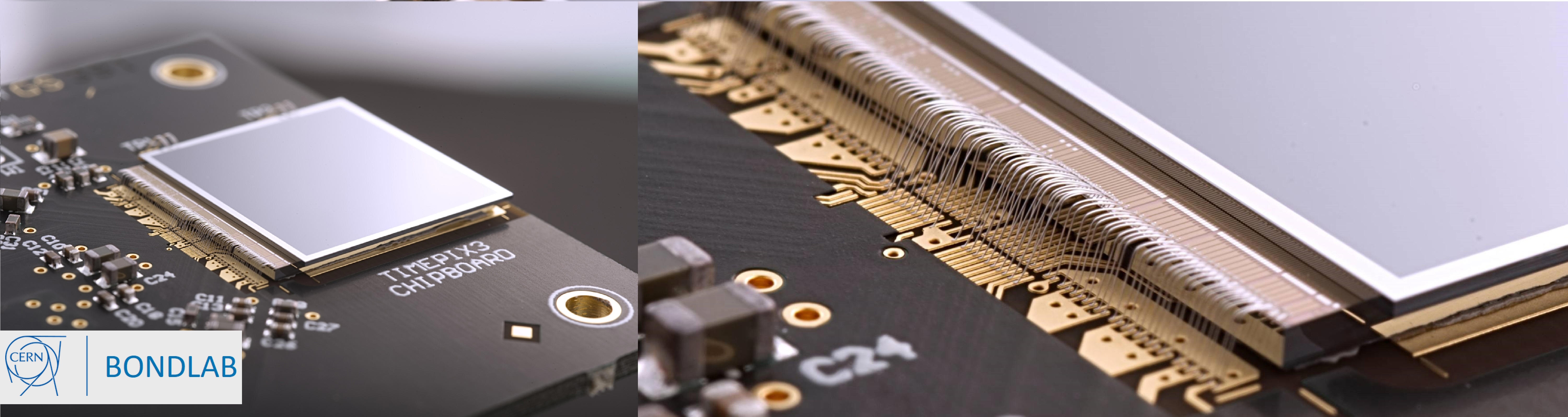
The bond surface
The
main criteria from the perspective of bonding:
The material and its
structure are compatible with the available method of bonding. In the case of
the Bondlab, the method used is Aluminium Wedge Bonding.
The bond surface should
be clean and free from all contaminants. Contamination sources are many and
varied, from the obvious such as a fingerprint to the more subtle and less
obvious.
The bond
surface should be flat and of a consistent thickness and quality with no surface
damage or irregularities.
The bond surface metal should be of a comparable
hardness to the bond wire used.
The bond surface metal is bondable. This can be
tested using the bond pull test.
Shape and Size of Bond Pads
This aspect of bonding is very much dependant upon the method of bonding that is
foreseen, Aluminium wedge bonds need a more rectangular bond pad form whereas
gold ball bonds favour a more square form pad.
It is not to say a wedge bond
cannot be bonded on a square pad, but one must keep in mind the pad size with
respect to the size and form of the bondfoot in three dimensions.
From a
Hybrid point of view it is prudent to make the bond pad as large as is
realistically possible. This allows a greater flexibility with respect to
placement of the bond, placement of the die and fiducial to bond pad repeatable
registration.
Pitch and Placement of Bond Pads
A
bond pitch of 60µm is possible with 25µm wire, but the loop will be limited in
height due to the nature of the Double Side Relief Tool which is necessary for
fine pitch Aluminum wedge bonding.
 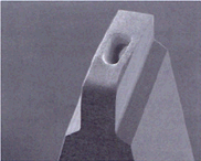
Double side relief tool ... another view
The
thermal stress effects on the first bond heel by the loop should also be
considered when making this choice.
The minimum preferable in line distance
between two bonds is 300µm, this is tool dependant and to a certain extent loop
dependant.
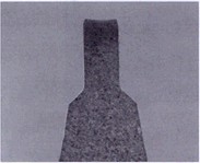
Bondhead Height Tolerances
Severe complications can result from electronic components (like LEMO
connectors) positioned too close to bond pads. Bonding clearance around the tool
of the 6400 is shown on this page.
The geometry of the bond head (tool, clamp, wire feed
tube, transducer etc., see below) poses restrictions on the height of electrical
components or any other objects in the vicinity of the bond pads (side
view,
3D view) made by Antoine Guipet).
Other Aspects:
Passivation
Backside of Hybrid / Pcb
Shape and size of bond pads
Pitch and layout of
bond pads
Passivation
of PCB / dies
Distance to high components
|